It is now time to change all the batteries (my oldest battery is 12 years old) and it doesn't pay to mix old batteries with new. In changing the batteries I intend to fix some of the (lack of) balance in the system.
One of the things I have done, is to have all three banks combined all the time. There are reasons for this; namely the bigger the bank and the smaller the discharge percentage before recharging, the more recharge cycles one will get out of the batteries.
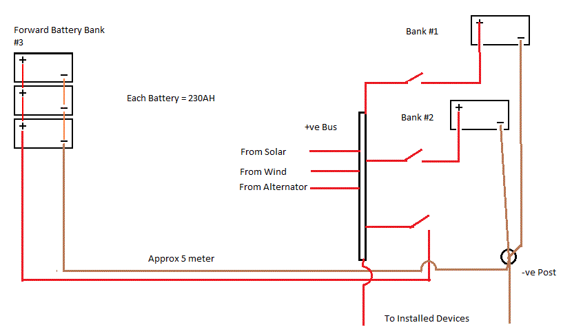
Here is a diagram of my boats wiring diagram for the three battery banks I have. I have been long aware that the draw from the 3 banks, which are always combined together is not balanced and the charge to the batteries is also not balanced. I'll try to explain.

A common method used to connect batteries, and then feed the load, are all taken from one end, i.e. from the end battery like in the diagram to the left.
The interconnecting leads do have some resistance. It will be low, but it still exists, and at the level of charge and discharge currents we see in these combined batteries, the resistance will be significant. In fact, it will have a measurable effect.
Often the batteries are linked together with heavy cable around 35mm. 35mm copper cable has a resistance of around 0.0006 Ohms per metre so the 20cm length between each battery will have a resistance of 0.00012 Ohms. This, looks like it is nothing to worry about. But add to this the potential 0.0002 Ohms for each connection, such as cable to crimp, crimp to battery post, we find that the resistance between each battery post is around 0.0015 Ohms. Plus the batteries themselves have an internal resistance of about 0.02ohms
So armed with that data we can then look at each battery to determine the draw.What ever we draw from this battery bank (say100amps), most would think the draw is evenly divided (25amps) between the four batteries. Least that's what we may think. But that's not the case; when you take the internal resistance and add that to the cable resistance the batteries supply a different amount. Without going into the calculations it would look like this
First battery draws 39.5 amps
The next battery up draws 26.2 amps.
The next battery up draws 20.4 amps.
The top battery draws 17.8 amps.
What can we deduce from these numbers? Clearly, the first battery is working harder than the last, but because the first battery looses capacity quicker, the other three will start to take more of the load. Because of the unbalanced nature of this battery bank, the bank as a whole will age faster than if it was properly balanced. Also the charging input works to the same inbalance; the first battery will receive more charge than the last battery in the line.
So how do we change the battery set up to give a more balanced draw and charge. Look at the next picture

What has changed in this diagram is that the main feeds to the rest of the installation are now taken from diagonally opposite posts.
It is simple to achieve but the difference in the results are truly astounding for such a simple modification of moving one of the connecting leads; everything else in the installation remains identical.
The results of this modification, when compared to the original numbers are shown below. It was simply done with one single connection being moved.
The bottom battery provides 26.7 amps of this.
The next battery up provides 23.2 amps.
The next battery up provides 23.2 amps.
The top battery provides 26.7 amps.
Clearly these numbers are better than those shown in the first example. But we can improve on this too.
One final method I'll present here gives a complete balance to the bank

It is quite simple to achieve but requires two terminal posts, by which the short leads, all which must be of the same length and size, are connected to the terminal posts.
The difference in results between this and the prior example are much smaller than the differences between the 1st and 2nd (which are enormous) but with expensive batteries it might be worth the additional work.
And here's what I have changed to (picture below). Simply, I have changed the interconnections for the batteries on Bank 3. Unfortunately, I can't do anything about one bank (#3) being so far from the other two.

- When motoring the alternator can supply to Bank 1,2, and 3, individually or combined. Because mine are usually combined, Bank 3 will lag behind in charging compared to Bank 1 and 2 (because of the small resistance in the long run to Bank 3's batteries). Solar and wind will not charge because my set point for the alternator is set higher than the wind/solar and therefor the wind/solar see's the batteries as being charged and dumps their load.
- Alternatively, when motoring, I can have Bank 3 turned off and have the alternator charge Bank 1 and 2; OR turn off 1 & 2 and charge #3.
- When at anchor with no motor going, wind/solar charges all three Banks.. I have the option of turning Bank 1 and 2 off to give Bank 3 a faster charge.
No comments:
Post a Comment
Note: Only a member of this blog may post a comment.